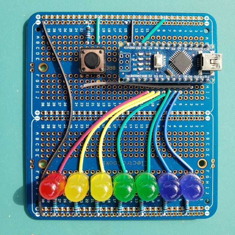
Here it is, in its blinky glory . So here’s the story, pandemic aside, I actually built one of these @ defcon 23. Disappointed in the record badge, Thursday night I went to my room and built a version not so different from this one. So when TDI went virtual, I figured I’d take a one-off badge “Off the Shelf”
This is not a comprehensive set of instructions for assembling this, but rather a set of quick reference charts.
| Build notes and BOM in a handy chart | ||
|---|---|---|
| Item | QTY | Location |
| PCB solderable breadboard | 1 | base |
| Resistors 220 Ohm | 7 | all to – rail J – 4, 8, 12, 16, 20, 24, 28 |
| LEDs | 7 | LED’s Blue H3,4 H7,8 LES’s Green H11,12 H15,16 LED’s Yellow H19,20 H23,24 LED’s Red H27,28 |
| Arduino Nano (clones are fine) | 1 | NANO C1-15 and G1-15 |
| Button | 1 | D20 & 22 and F20 & 22 |
| 10K Ohm resistor | 1 | 10k -Rail & B22 |
| wiring chart | ||
|---|---|---|
| Part | Connection | Note |
| Blue LED var blue01 | F3 – I5 | should line up with pin D8 on the arduino |
| Blue LED var blue02 | F7 – I6 | should line up with pin D7 on the arduino |
| Green LED var green01 | F11 -I7 | should line up with pin D6 on the arduino |
| Green LED var green02 | F15 – I8 | should line up with pin D5 on the arduino |
| Yellow LED var yellow01 | F19- I9 | should line up with pin D4 on the arduino |
| Yellow LED var yellow02 | F23 – I10 | should line up with pin D3 on the arduino |
| Red LED var red01 | F27 – I11 | should line up with pin D2 on the arduino |
| board power | B12 – +Rail | should line up with pin 5V on the arduino |
| board power | B14 – -Rail | should line up with pin GND on the arduino |
| Button 1 | B20 & +Rail | Provides current so the button can be read |
| Button 2 | H22 – H3 | should line up with pin D9 on the arduino |
